I am also recording this output on the computer next to it, and hope to get my 10 channel super fast hi rez soundcard going soon so I can do analysis on it all later.
One of the things this is showing me right now, especially in conjunction with the new preamps/power supplies for detectors, is just how variable the fusion rate is, even when all the meters are stable, all the counters are reading about the same -- all that stuff has too much time averaging in it to see what I'm "seeing" with my ears and no averaging. If what I'm seeing is correct (it is very repeatable anyway) then if I could just get the fusor to sit on the peak, instead of drifting all over, I'd be seeing nearly 10x more average output. But you can't even see that variation with most techniques -- easy with this one. I didn't think of this myself, of course, I simply added the idea of stereo and fairly high fidelity to the old geiger clicker.
During the short time over which this scope trace was generated, you can see (and I heard) considerable output variation, that a counter, even a one second period, would just average out.
And in fact, that's how I knew to "pull the trigger" on the scope snapshot without even looking down at it. That's the beauty of this.
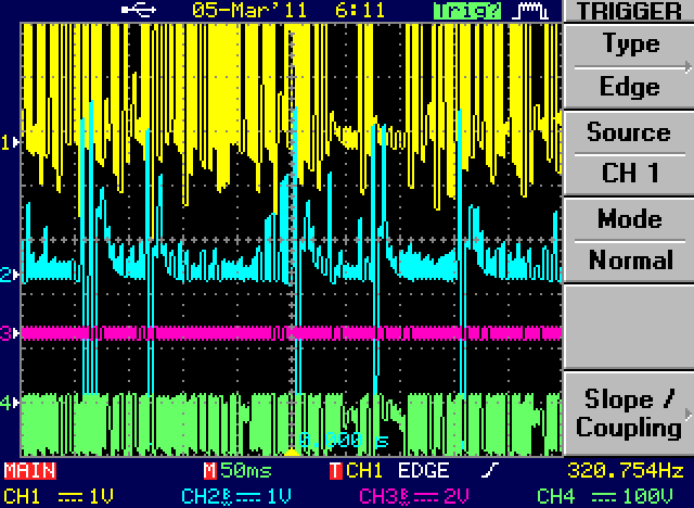
- Example from the scope
- stereoneuts3.png (5.77 KiB) Viewed 2812 times
Top trace is 3He tube, next is B10 tube (lots less sensitive and farther away too) purple trace is NC, and green trace is a faraday probe in the tank -- showing that when we're running strong we have large net negative charge in there -- excess electrons. The upper two traces are somewhat corrupted by the audio amp, which is AC coupled, In both cases the real tube output is the positive going pulse, the negative undershoot is from the cap coupling and a protection diode in the amplifier. While not trivial to see in this picture, I've noticed that the onset of fusion after a dead spot has exceptionally high output. In another thread here, I've posted about "driving" that instead of just letting it happen randomly, with some success -- it's the road I'm now traveling down.
Here's a scope trace that shows that. Top is a neutron detector, bottom is volts on a secondary grid inside the tank, driven through a capacitor from a neon sign transformer. Note that it can't make positive voltage -- it's busy collecting electrons. Then when it goes negative again, we see a bunch of neutron output in bursts, that are matched by bursts on the NST waveform. Those kinda have to be large groups of positive charge forcing that high impedance up to positive voltages, even though the NST is trying to drive it negative at the time. Should also be obvious that 60 hz sine isn't the ideal drive for this, but it was easy, so I tried it.
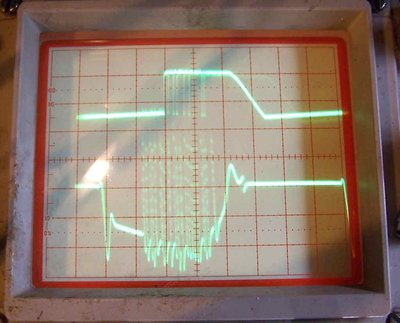
- Neutrons synced to drive waveform on 2nd grid
- SyncPulses.jpg (25.69 KiB) Viewed 2812 times
There are a number of things in this waveform I can't yet easily explain, but it's encouraging. During this, the main supply current was in the .1 milliamp range, yet I was getting as many neutrons/second average as with 400w inputs. The top trace shows some corruption again due to the coupling caps in the audio amp and the resting DC value of that particular preamp, but you can get the idea.
FWIW, the things I think are interesting here and can't explain are:
1. Why does it go positive for a little while with the NST? Electron collection should start much faster than this sweep speed could even show, not a millisecond! Should be in the many mhz speed range, like any other vacuum diode.
2. Why did it take so long once the 2nd grid goes negative to start pulsing? It's reached ion source status a long time before that first burst.
3. Why are the burst times so short, but so long in between?
All these times are eons compared to computed transit times in these fields.
At any rate, I now have an arbitrary waveform generator to play with and that 1.5kw amp to drive transformers with said waveforms. You'd think the times should all be in the RF range, but we see what we see, so I'm simply getting ready for both. The wave generator goes to 125 mhz sample rate (it's basically a modified VGA card) and all the way down to millihertz.
If I can learn anything encouraging down at the audio range, I'll finish building that video amp I've been working on and move on up. The challenge there is more the output magnetics than anything else. If I had a clue what frequency I'd be working around -- trivial. But designing for octaves of bandwidth isn't by far so easy. I may have to just build a bunch in various bands.
Posting as just me, not as the forum owner. Everything I say is "in my opinion" and YMMV -- which should go for everyone without saying.

