Coax has two limits in power handling, current and voltage. At the lower impedances you are asking about, it's going to be current limit mainly as the volts will be low for a given power.
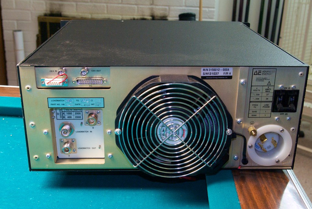
Classic RG-8 kinds of coax, the fat stuff, will typically take some kilovolts without arcing -- often a lot more than the RF spec indicates, we use it here for HV DC because of that. The connectors on your RF box would indicate that's what it was designed to use. Not the skinny RG-58 class stuff, you'd have issues with that.
At current limits, what you'll see is heating of the coax, which can melt the center insulator and allow the center conductor to migrate in there to the point of shorting. This is from skin-effect
resistive loss in the copper of the coax. In extreme cases we go to hardline -- air (or vacuum or dry N2) dielectric and just a rod in a pipe -- rigid so it can't flex. A pain to work with too because of that.
Coax (or any transmission line) has a nominal impedance rating. An infinitely long piece of 50 ohm coax will look like 50 real resistive ohms from an end no matter what is at the other end.
But in lengths much shorter than 1/4 wavelength of the RF (at the speed of light in the coax which is around. 6-.8 of C-vac but varies with type, a lot), it just looks like a capacity in parallel with things that is easily "tuned out" for a fixed frequency to get a low Standing Wave Ratio or SWR.
As you go up in frequency, it matters more, because the length at which these effects kick in is shorter -- at 1/4 wave for a given frequency, a piece of coax that is shorted at one end looks like an open circuit at the other end, and is often used that way for impedance matching or even ultra-high Q tuned circuits. For a quarter-wave impedance matcher, if you have A as impedance you want to match to B impedance, you use 1/4 wave of coax or other line that has the geometric mean, or sqrt(A*B) impedance for least losses and perfect matching. You will find this trick used in many ARRL handbooks to match some oddball antenna impedance to the feed-line over a narrow band, and a version of this trick is used in my microwave ion source (not yet posted on the board) to match the impedance of the magnetron to that of the gas system/plasma we are trying to ionize. I will try and get a link to some ARRL handbook up here shortly, as there are a few online for the downloading, and they have maybe the best/easiest/simplest explanations of all this that exist, in them -- if you get one from the years when Hams still built most of their own gear, meaning usually, not the more recent editions. Working backwards from about the '70s is where you'll find the good stuff, back to about WWII era.
As far as feed-throughs to vacuum, go for the big ones -- type N etc and you might have to modify them a little to keep them from arcing (or just lighting off a plasma) inside the transition. You can often avoid that by use of Paschen's law, where it takes a counter-intuitive longer gap to get a gas to "light off" at low pressures than the same voltage will do at higher pressures. Otherwise you may have to add some solid, low dielectric constant (and low loss) insulator there to keep the insides of the feed-through from having issues -- teflon if you are brave (it fails spectacularly when it fails), or quartz. I note that 1/2" quartz tubing fits over the center conductors of the type N FT's I've got here. It spoils the impedance a very small amount at these lower frequencies -- not noticeable at 0.450 mhz, and barely at 13.56 mhz. At real high frequencies it looks like you added some capacitor to ground there, enough to matter, perhaps. Shouldn't trouble this application, and I notice that real complex impedance matching isn't in your RF supply -- actually, a good sign, means they designed the final output to handle lots of this mismatch without needing help. Most real world things don't have a pure R impedance (and plasmas are as bizarre as it gets), but have components of C and L as well and that messes up RF amps near the power limits, as they see either more current or voltage load or out of phase load (leading or lagging) than the design center for them. These things, meant for this use, seem to have been designed pretty conservatively and don't mind a little of that. Good! You could think of this source as being designed for "high torque and rigidity" in machinist terms.
For induction heating -- there's a frustrating lack of good info out there (other than first-principles stuff), even in some pretty good books you'd think would have it, from the American Welding Society series to Kohl's Handbook of Materials and Techniques for Vacuum Devices -- both of which mention this as the best way to do vacuum heat treat or brazing. But the principles are clear anyway. What you are trying to do is create heat in a conductor via putting it in a changing magnetic field, and making it a "shorted turn" in a transformer. Penetration depth of the heating is related to the "skin effect" phenomenon, which is thinner the higher the frequency -- 60 hz will heat large object all through, higher frequencies just deposit energy into the outer skin, so you can control some of this with frequency. Your coil will have some of these same losses, not being an infinitely-thin superconductor, and most real world induction heaters for vacuum brazing or whatever have to be made of water-cooled Cu tubing to live. Even the fact that your coil conductor-pipe has finite thickness means the H field will not be the same on the inner part of a turn as the outer part -- and that will heat the coil from resistance losses through its own cross section!
What you are trying to do is impedance-match the load to the supply, as well as you can, and deliver the most current per turn into the workpiece you can, as the workpiece is "one turn" at whatever conductivity it has, which, BTW, varies a lot with temperature for most of them. This usually means you want a coil inductance that amounts to a higher impedance than the source when it is unloaded by a "short circuit" workpiece, and that at 50 ohm more or less source, your source will be higher impedance than the workpiece, so you have a coil of enough turns to step down to that workpiece for best match (this is analogous to a gear ratio). So you are making a step-down transformer from your source to the load, with more than one turn in your coil used to accomplish that. Most of the ones I've seen use a few turns of coil for this, but at least one kludge I've seen uses many-many because they used a very high impedance source (and that one was so hard to cool, it's a one shot per hour thing). That one used a line powered H bridge driver at the 10's of Khz.
Further, the eddy currents you produce in the workpiece make their own H (magnetic) field, which is repulsive to the applied field, and can actually toss the workpiece around if not held down well, in reaction to the field from the coil! We are not talking about weak fields in this game.
There are a lot of tricks for concentrating or shaping the net field to get what you want, so only the part of the workpiece you want gets the heat, and it doesn't fly out of the jig. Also, that frequency dependence. So if you want deep heat treat, you have to either go to lower frequency for even heating below the skin, or take longer so the heat seeps into the core of the piece. But this may be just what you want -- you may only want to heat the surface; often (errm) the case for hardening.
Since there's so little out there on this -- trade secret territory -- I think we're going to wind up writing the book, here, ourselves. I like doing things like that, they shouldn't be secret.
Basically, if you've got a 50 ohm source, you'd want a coil inductance amounting to an impedance of several times that at the frequency of operation, with no workpiece present, so you can use the inductor design tables in many books to get in range. EG you might want a coil impedance unloaded of a few hundred ohms at the frequency you're running, which will come right on down when a shorted-turn workpiece is in there.
Even 450 khz is on the high side to heat much more than the very thin outer skin of a piece -- if you wait long enough, the heat will of course conduct inside it, though.
Although your source is probably pretty resilient to mismatch, I'd advise getting (or making) an SWR meter for this frequency/power level range. It will make what you have to do obvious to get a good match and get the heat where you want it, rather than in your source. Eg add or subtract a coil turn and see what matches best -- now you know which way to go.
Some RF books online here that should help you. Particularly the old ARRL handbooks.
Posting as just me, not as the forum owner. Everything I say is "in my opinion" and YMMV -- which should go for everyone without saying.