Coulter's Smithing Home
Vacuum conductance servo valve
Nearly all fusors, and a few other processes are run in a flow through mode; there is alway gas being let in, and being pumped out.
For a given pump speed, you could get a certain pressure by controling the gas inlet, the pump effectiveness, or both. To have a fixed pressure, but also have control over the net flow rate, you probably need to control both, or that's what I find here. As conductance valves are not inexpensive items, and tend to require a fair amount of space in the pump stack which I don't have to spare, I designed and built this valve to fit basically into the pump throat, or actually inside the bellows just above the pump. Being inside the tank means I had to make it a servo driven type so it could be adjusted while running.
The idea here is to have the full pump flow, or nearly, available for initial pumpdowns and bakeouts, but then be able to run the fusor with a controlled amount of flow through at low flows to both save gas and keep some of the more desireable reaction products around.
The big turbo helps with this some -- as a kinetic pump it will preferentially pump the heavier gases better, and this effect seems best when it is spun down some. Unfortunately, when we spin ours down as far as possible, it's still too much pump with the forepump running, not enough with the turbo just switched off, and our nifty control scheme for the forepump isn't ideal anymore -- takes a lot of messing with the pump UI to control the forepump with turbo rotor power as we do in the full blast mode. At low rotor speeds, the thing just doesn't draw enough power to make the switching reliable, and in that mode the goodness of the pump system changes a lot with foreline pressure, which results in unstable vacuum control. This project was meant to let us just run the pump in normal full speed mode, or nearly, and control the flow another way.
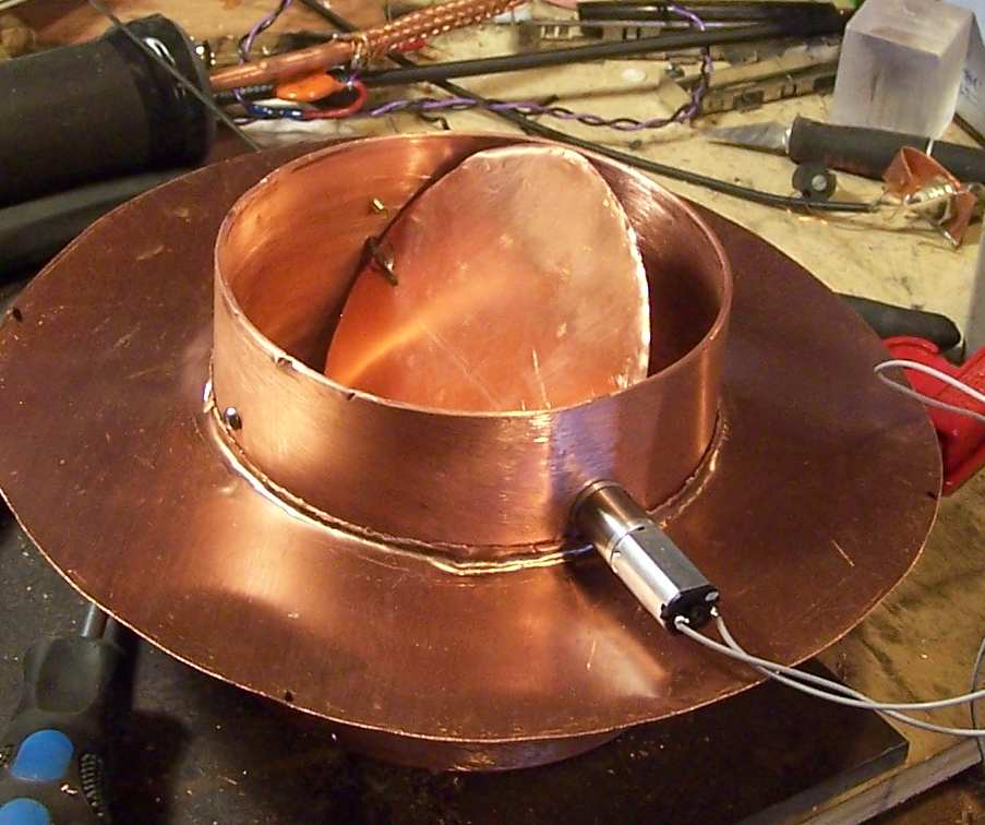
As you can see, what I've built here looks a lot like a butterfly valve from a carburetor. Yup, same idea. Here I am hoping I can get away with somewhat less precision, as the application should be able to tolerate a certain amount of "vacuum leak" at "idle". Should this be too gappy, I have plans for inserts to make it seal better closed. The biggest design constraint here is that the thing has to fit through the 6" door, and then fill and overlap a 6" hole. I plan to accomplish this by just folding the ring around the pipe up and then flattening it once inside the tank. Should that not work, I can take off a large flange and pay for another really expensive gasket for that, but we can hope, as this shouldn't have to be all that great a seal.
 Had I not cropped this, you'd see just how messy my "desk" really is -- which would give some people a heart attack. But you know what they say about a clean desk vs the contents of the mind, so I'm happy. I found these really neato little servos surplus at Marlin P. Jones for about $15. Their distinguishing factor is no obvious oil in the gear head, and sheet tiny-ness. All metal gears, they are very nice, and in this case, way overpowered for this use, so the usual vacuum stiction shouldn't hurt things. Being a PM DC motor, you just reverse the polarity to reverse direction. These are rated at 12v input, but even 6v is on the high side, so I will build a little supply that puts out plus and minus 6v with a surge current ability for jogging, but then a lower output for running so I can get some fine control. At 12v this motor is about 150 rpm -- too fast.
 Being an effective cheapskate, I made this out of the motor, one piece of copper flashing did the butterfly and outer ring, and one 4" piece of 4" ID Cu pipe. A few small details round out the parts list -- a few 4-40 screws, a little chunk each of Al and Fe for the motor shaft clamp, and yes, a piece of baling wire for the other butterfly valve pivot. You can see the bit of wire soldered to the butterfly at the back of the picture. The reason both pieces of flat copper have lips on the edges is because I cut the inner circle out of the outer one with a cold chisel on an anvil. This worked out nicely as this helps the big ring grip the pipe (whether I braze that on is yet to be determined) and stiffens the butterfly enough so the motor can't twist it all up when it hits one of the stop screws shown, at the left for the closed position and at the back for the open position.
|
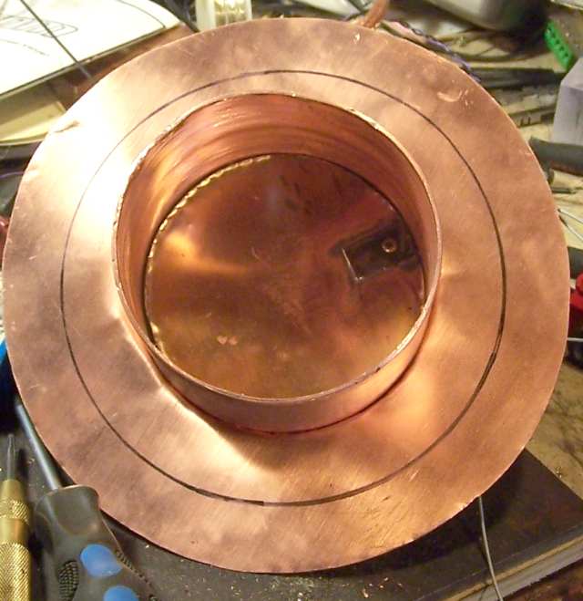 There are probably a few other ways to get mounted on a tiny, short, metric flatted motor shaft that are better than what I did, but this does work fine. Basically I just clamped it. To do that, I cut a small piece from a piece of Al bar stock, about 1/2" by 3/4" by 1/8" thick, and tapped it 4-40 for a clamp screw. This kind of worked, but needed improvement, as the copper butterfly was able to bend under torqe and let the shaft slip. The quick fix was to make a steel piece for the other side and solder that on there for stiffening, and cutting a small file groove in the Al piece to positively locate the shaft and its flat. It has now been tested for a few hundred cycles on the bench without troubles, so it's about to go into the tank. The big black circle on the outer plate is the size of the hole I have to fit this through. I plan to just fold the sides up, then back down once inside the door, as this is also the size of the hole it's going to sit in, and this plate is intended to be the "seal" if you can call it that. I am hoping this setup will tolerate a fair amount of "leak at idle" and still do the job we need. Obviously improvements are possible if not, but why get too fussy upfront? Even with a small leak here and there, we'd be cutting a 6" diameter pump throat down to a fraction of one square inch, leaks and all, which might be just fine for the intended use.
Here we are looking at the bottom side of all this - this part will go down into the hole the pump bellows mounts to, and there's plenty of room down there, so no reason to waste in-tank space here. I will lose some full speed capability here, but a lot of experience with this setup says that won't matter much at all -- we have considerably more pumping capability than we really need, with the system normally hitting 1e-6 millibar in a couple of minutes from atmosphere, and getting down to the e-9 range overnight with some baking. Much more than good enough for beams and fusors, so I am hopeful this will work nicely.
|
Assuming this works out with a manual control, I will hook it to one of the many control computers we use here and have that regulate the valve position based on feedback from other things, from vacuum gages to power supply currents (more sensitive). For now, I will make a "squishy" power supply with a wall wart with a lot of series R, so the motor will just run, and add a capacitor to the supply output that will take full charge between motions to provide a little extra kick at the start of motion to overcome any stiction, which mechanical things in vacuum are famous for. This is for example why I used a different material for the pivot (the baling wire) as copper to copper vacuum welds are easy to make by accident when things get really clean in there. And they do in a system with hot hydrogen as the main non-vacuum component. I did not worry too much about using a little solder in this, as it will sit where the temperatures stay fairly low. Should that be a mistake, there's always the Cd-free silver solder on the shelf. My mass spectrometer will tell if there's a problem there (or worse, it just melts). I have gotten away with using plain old solder before in similar conditions, as long as it's cool where it is and kind of out of the strum and drang, it works fine.
Since this hasn't been into the tank so far, obviously I can't yet report on how well it works. But here we have to do some "cowboy science" to make progress, and agonizing over design doesn't get 'er done, so we make things like this, try them, and them modify as needed. Too empirical for some, I know, but it works out well here as a technique to make progress fast. As I get more experience, things have a better tendency to work on the first try anyway, so I can hope this will, or at least not need extensive mods to work.
If it leaks too much in the closed position, I can braze in some lips on the main pipe to help labyrinth seal around the edges of the butterfly, for example, but if that's not needed, well, I saved some time and effort by not doing it yet. Having those in there would make it harder to put the thing together, so leaving them out for now is a design decision made on purpose.
The jury is out for the moment, but "nothing beats a failure like another try" so here goes.
Back to projects
Coulter's Smithing Home
Here's how to contact us:
Contact information