 Here is a picture of the parts we used in our first try. We did indeed learn a few things doing this!
In this picture is shown the one hard to make part, the copper inner conductor with the mounting facility, O ring grooves, as well
as the very easy to cut glass/quartz pieces we began with. In this picture, the larger diameter piece is pyrex, while the smaller piece is quartz. One of the issues we had to deal with in the design is that glass and quartz come in a set of sizes, and so do commercial tubing couplers, and obviously to get a seal, they have to match somewhere. We used a 1 inch outer glass here, and a coupler to match, all very standard sizes for those.
Here is a picture of the parts we used in our first try. We did indeed learn a few things doing this!
In this picture is shown the one hard to make part, the copper inner conductor with the mounting facility, O ring grooves, as well
as the very easy to cut glass/quartz pieces we began with. In this picture, the larger diameter piece is pyrex, while the smaller piece is quartz. One of the issues we had to deal with in the design is that glass and quartz come in a set of sizes, and so do commercial tubing couplers, and obviously to get a seal, they have to match somewhere. We used a 1 inch outer glass here, and a coupler to match, all very standard sizes for those.The inner conductor was a piece of 3/8 inch OFHC copper rod, drilled and tapped for 10-32 on both ends, brazed into a shorter piece of 1.25 inch billet OFHC copper at the fat end, which is what got all the lathe work. We cut a groove for a Viton O ring for sealing in the larger piece as well as turning it down to fit inside the glass for part of its length. We use an additional O ring around this not for sealing, but simply to cushion the interface between the end of the glass and the flange on the fat copper piece, which eliminates any need to polish the end of the cut glass tubing. As you can see in th picture, we also cross drilled the copper rod behind the tapped hole in the end for quick pumpdown.
One thing we found out fairly early on in this is that anything going between your conductor and the rest of the tank had better be able to stand off the full voltage all by itself. So when we had the smaller, thinner walled quartz extend beyond the end of the thicker pyrex, basically right out to the end, it would collect ions until it would arc through there, eventually destroying it, and trying to take some expensive power supply gear along with it. However, recessing the end of that back about half an inch solved that one completely. We also found out that due to Paschen's law, you can have arcs down the full length of the inter tubing space, and trying to insulate back at the atmoshpere end with an inserted teflon plug led to the same conclusion -- each layer has to withstand the whole applied potential, or it just picks up ions until arc through occurs on it, and with teflon that's a big no no, it releases all kinds of nasty byproducts into the vacuum, and also carbon tracks and becomes conductive. However, once that was understood and taken care of, the design was vindicated, and has now made something like 50 full fusion runs without any troubles at all. I selected copper for this first one, even though the stuff isn't cheap, as I wanted to look at conducting heat out of the tank, being able to braze or solder it and so on. The next rev uses aluminum, as the copper just isn't needed for this, and the Al, as any machinist knows, is one heck of a lot easier to machine.
 Here you can see the thing in use, as it is at the time of this writing, Jan 2010. You can see the little teflon button I turned down to insulate the end from long arcs, and the gorilla tape used to keep it from creeping into the tank if someone used a little grease on the tubing coupler. One nice thing about these is that you can push or pull them to get a position in the tank you desire and not have to break vacuum to do it. In this picture, we are testing a new ballast resistor, which we mounted simply by cutting a short piece of Cu tubing as a clamp and shoved one end onto each thing. Cowboy lab technique, but this was for a quick test of the resistor, and will be improved now that we know it's worth the effort. In the background is the microwave/ECR ion source we use, temporarily missing the little polycarbonate box we put on it to keep arcs from happening. I sometimes have kitty cats in the lab....they do seem to know enough to stay clear when the high voltage is on, I think they can hear the corona or something.
 Here are some ancillary items we use with these. The big copper pieces are for corona ball use, and heatsinking, and both work fine so far. We also use pipe clamps, insulating sleeves, and insulating disks, depending on what we have hooked on the end. The end of the feed through is also tapped 10-32 for using plain old lugs when that's best for our application du jour. In the back right you can see a teflon plug that didn't make it -- an arc snuck past it and blew out a chunk. Gotta be careful with a lot of stored energy!
I had tried this on the vacuum end of things before learning to just cut the inner quartz tubing shorter, which solved all the troubles I had. I now accept a slight loss from ions hitting the exposed part of the Cu in the tank, it's not a biggie.
Here are some ancillary items we use with these. The big copper pieces are for corona ball use, and heatsinking, and both work fine so far. We also use pipe clamps, insulating sleeves, and insulating disks, depending on what we have hooked on the end. The end of the feed through is also tapped 10-32 for using plain old lugs when that's best for our application du jour. In the back right you can see a teflon plug that didn't make it -- an arc snuck past it and blew out a chunk. Gotta be careful with a lot of stored energy!
I had tried this on the vacuum end of things before learning to just cut the inner quartz tubing shorter, which solved all the troubles I had. I now accept a slight loss from ions hitting the exposed part of the Cu in the tank, it's not a biggie.
 Never being content with a first try led to this variation on the basic design.
 As noted above, these tubings and couplers come in the sizes they come in, and the revelation that a single thickness had to stand off the full volts, along with the idea of wanting a lower dielectric constant for less stray capacity, I looked for 1" thick wall quartz in vain. Found some thin wall stuff at the 1 inch OD, but no thick in that size. But I did find some thick stuff about 3/4 inch, so I used that and used some thin wall stuff to adapt to the tubing coupler. To do this elegantly required some quartz welding, which was fun to do once I'd built the right tiny but very hot torch to do that with, which I hope to put up here as another project at some point. The near end is welded airtight, but the far end is not, I deliberately left that leaky, because I was seeing water from the torch flame condensing between the tubes and didn't want that sealed in there too. That part only needed enough for mechanical stability. To do all this I made a lathe jig to chuck in the tailpiece and shrunk both ends of the 1 inch tubing around it to fit the smaller stuff, then did the welds on pieces that already fit perfectly.
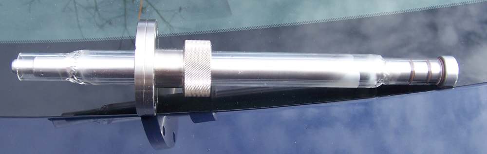 Here is another view of the result. This model has a piece of billet aluminum, 6061-t6 turned down as seen here.
This allowed for a much thicker main rod, so the heat conduction is still good, and no chance at all for it to leak at a joint,
because there aren't any joints. I used two O rings here more for alignment than anything, and may run with just one of them. You
can see a third one at the end of the quartz -- this doesn't seal at all, it's just a cushion so I don't have to polish the tubing
end for strain relief, or fire polish it and risk making it shrink and not fit. The clearances here are fairly tight.
The frosting you can see here is a normal result of the temperatures needed to really work quartz, or so say
all the books I have on the topic. It does not seem to hurt anything.
Here is another view of the result. This model has a piece of billet aluminum, 6061-t6 turned down as seen here.
This allowed for a much thicker main rod, so the heat conduction is still good, and no chance at all for it to leak at a joint,
because there aren't any joints. I used two O rings here more for alignment than anything, and may run with just one of them. You
can see a third one at the end of the quartz -- this doesn't seal at all, it's just a cushion so I don't have to polish the tubing
end for strain relief, or fire polish it and risk making it shrink and not fit. The clearances here are fairly tight.
The frosting you can see here is a normal result of the temperatures needed to really work quartz, or so say
all the books I have on the topic. It does not seem to hurt anything.Assuming this tests out well, this is the version I would make for others to use, it's a good balance between performance, materials costs, and labor to make. The only part that should ever fail would be the quartz, perhaps due to having metal from something sputtering in the tank condense on it, and it being some metal you could not easily chemically strip off. That's another advantage of this design, by the way -- you can take it apart and dunk the quartz into some acid you'd never apply to any of the other parts were you in your right mind. In theory, this is an advantage of the aluminum too, it does not sputter under ion bombardment nearly as quickly as nearly all other metals do. Testing in real life will tell. I made this one as we wanted to improve on another fusor we are working with here anyway, and the one on the big tank works fine, so we didn't want to steal it for that. Having two can also allow for split supplies to be used safely, with the tank still grounded, for things like beam on target experiments.
As usual, contact us if you can't make one yourself and can't live without one either. These have been tested up to 53 kv plus any big spikes and they just don't notice it at all.