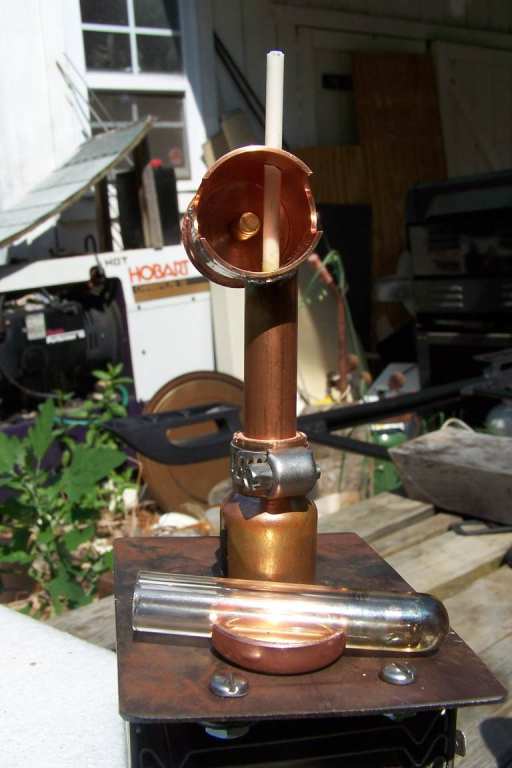
 This is the finished unit on a test jig, in operation with deuterium feed. We have added several important features to the original design. The biggest one is the magnetic field that gives Electron Cyclotron Resonance, which allows this to light off and stay lit from atmospheric pressures down to 1 e-6 millibar or so. We also added a controllable ion extraction field in pushme-pullyou fashion, controleed by a variable voltage split supply based on a CCFL inverter and some rectifiers and filters, so we have continuously variable ion injection to the main tank. We retained the ability to remove this and work on it without breaking the vacuum as in the original design, and were able to do it in a way that doesn't need forced air cooling for the cavity to boot, as the original design needed.
The net result is that this is more efficient, works over a broader range of pressure, and is more controllable than the original design by far. It is also pretty cheap to build yourself. Most of the "exotic" parts are from a dumpster, the rest are mainly from the local hardware store or McMaster-Carr. The single hard to make part is the cap threaded for the tuning screw, the rest is all hand tool turf. Even the cap could be replaced by a copper pipe cap with a nut brazed on if you wanted to go the hand tool route fully. It's just that I do have a machine shop here, so I take that into account when a few seconds on a real tool may save an hour of hand work with a file. In this case the machined end cap also has some electrical advantages over the pipe cap and brazed nut approach, as where the tuning screw joins the cap is the high current node in the resonant cavity, and a good solid ground is very important there to avoid losses and heating.
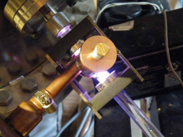
Before we start discussing the individual parts and how to make them, let's do an overview of what we are trying to make, which the above picture is ideal for. This design involves coercing a normal microwave oven magnetron into operating in continuous (CW) mode, rather than the pulse mode it was designed for, which can sometimes be a trick to accomplish. Fortunately, we only need a couple of tens of watts out of it to do the job, so it is possible without getting into some failure mechanisms magnetrons have in CW mode. In the picture above the tube itself is cut off at the lower left. The pipe adapter and pipe coming diagonally up from that corner are the adapter and transmision line for the RF to the cavity. You can see it enter the cavity more tangential than normal, a feature of the original design that we didn't change -- it works well. One modification we made on the original was the variable length of the hardline -- that is what the pipe clamp accomplishes. We found that trying to tune the coupling screw at the end through a hole in the cavity as in the original was very problematic -- anything we used to poke in there affected the tuning badly, and some lossy dielectric tweakers just burn up quick. As it turns out, tuning this aspect is pretty non critical anyway, and once set hasn't needed to be changed. Moving up to the cavity proper, we have a piece of 1" ID copper plumbing pipe for this. The top is the special end cap used to hold the 1/4 wave stub which is threaded for tuning. At the other end is used a standard pipe cap that is cut down shorter, and notched (along with the 1" tubing) to allow the quartz pipe to pass through the cavity at the high voltage node end. To provide the roughly 980 Gauss magnetic field needed for electron cyclotron resonance, we built an adjustable magnet/yoke structure that is also threaded by the discharge tube. We bought a hall effect magnetometer to adjust the magnet spacing to get roughly the correct field for electrons to resonate with the 2.45 GHz output of the magnetron. Barely visible at the lower right is the cappilary tube we let gas into the system though, which also servers as the pusher electrode part of the ion extraction system. Not visible in this picture is the other electrode, which is inside the main vaccum tank, slid into that end of the quartz tube. Adding this and the magnetic field turned out to be very major improvements to the design, allowing use of less microwave power, longer gas pressure operating range, and some very nice control over the ion injection rate into the system.
 This is the picture everyone seems to want to see, as if there's some sort of wicked black magic inside the cavity. Nope, or not much anyway. This is a simple 1/4 wave transmission line (coax in this case), shorted at one end, input power coupled somewhere along the middle, and that's it. The tuning screw controls the length of the inner conductor (it IS the inner conductor) so we can adjust to 1/4 electrical wave despite there being some changeable dielectric in the cavity. In this picture you can see how the notches were cut in the outer conductor (pipe) and the shortened cap. The white rod is alumina, and at first was tried as a way to adjust the length of the inner conductor from the magnetron. This did not work out -- alumina is too lossy and has too high a dielectric constant for this use and simply caused arcs. I wound up simply drilling and tapping the inner conductor of the hardline and putting a 4-40 screw in there, and adjusting with the power off. As it turned out, it only took a few tries to hit a place where it works and hasn't been adjusted since. We did discover that we had less trouble with arcing if we smoothed off the end of the tuning screws in this, just a file on the lathe to take the threads down and round the ends did it well enough. In the picture, and in the icon leading here from the projects page, you see some glass tubing, in this case 7740 pyrex. That did not turn out to be very good at all, its only advantage being the ability to make a glass to metal seal. Pyrex has a heck of a lot of loss at 2.45 GHz, ours was too thick for best gas volume in the cavity, and just wasn't anywhere close to as good as 1/2" quartz turned out to be.
When this picture was taken, I had not yet drilled and tapped the cavity top and cap at the bottom for 4-40 screws to hold it together, and frankly, look cool too. They weren't needed, but do serve to hold the thing together in real field use so things can't shift and require re tuning. And this cavity is high enough electrical Q that tuning is important here -- once you find the spot, the useful range is perhaps a 45 degree rotation of the 1/4-20 screw, which we put a spring under the head of so it would be stable. It works, and we've very rarely touched any adjustment in hundreds of hours of runtime. This Just Works.
If there's any black magic here, you can't see it in any picture I have just now. It is in adapting from what was supposed to be an antenna to feed a piece of hardline coax. There actually wasn't much to it, though (leaving the theory aside for now). I brazed a pipe size adapter into a piece of common sheet metal you see bolted to the magnetron here. The adapter sticks down into the ground gasket about 1/8" or so, with the spring in the sheet metal holding it tight against the magnetron. Next, a washer was brazed on the end of the center conductor, which here is a piece of 1/8" Cu pipe. This in turn was soldered using some special flux for stainless steel we got at McMaster, to the end of the tube "antenna". The net result is a transmission line to the cavity that is roughly 3/4 wavelength, which is electrically the same as a 1/4 wave line would be for RF impedance matching purposes. The outer conductor is a piece of 1/2" Cu tubing, which needed a bushing to fit tight into the pipe adapter, which was slit on a saw and clamped with the hose clamp as seen. Note, for whatever reason, when you say "pipe" the assumed dimension is ID, but for "tubing" the assumed dimension is OD, and here I'm just perpetuating that strange nomenclature, which is industry standard for whatever reason. For reference, the coupling adjustment worked out such that the center conductor of the hardline is just about flush with the edge of the cavity. In the case of this one, it's a 4-40 screw threaded into the end of the 1/8" tubing that has been rounded off so no sharp edges to start arcing. It's not critical, and anything plus or minus something over 1/6" inch is fine here in this lashup anyway. YMMV when using a dumpster magnetron or one of a different basic power level. I very much reccomend using the lowest power magnetron you can find for this -- you just don't need even what that can put out, and they are somewhat difficult to "throttle" as well as could be desired. There is kind of some hysterisis in this, the bigger tubes have a higher mimimum power they will work at, and even this is borderline too much with a 600w rated magnetron.
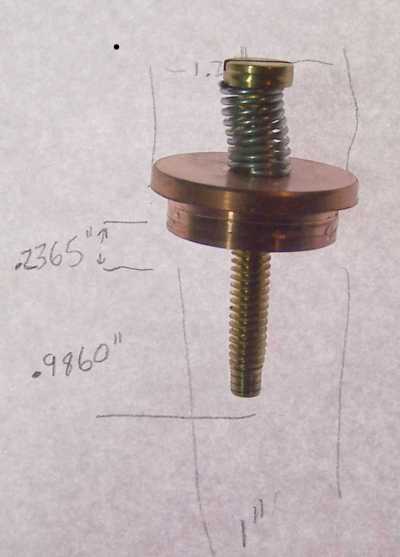 Here is some detail on the fabricated end cap and tuning stub. The screw is brass from Lowes, about 2" long total. We put a spring under the head to keep it from being wobbly and to make tuning more stable along with having definate pressure on the screw threads to get a good connection there. In this picture you can see how we rounded the end of this to reduce some arcing problems we had when running with the very-inferior-for-this pyrex instead of the quartz we use now. Dimensions are on the paper in the background to help you get the thing adjusted right on the first try. There is nothing magic about the length the cap protrudes into the cavity, this was just a convienient amount.
 The net inside cavity length is the key dimension to get to, however you do that. It is not extremely critical, however. The idea is to make it as short as you can and still have the 1/2" quartz tubing clear the tuning stub end. Here that worked out pretty close to 1.75" internal length. The idea is to have the highest possible E field per cm right where the gas tube is, so a closer fit means more field on the gas to ionize it for the same power, between the end of the rod and the end of the cavity. As we can easily have too much power here, this isn't critical at all unless the cavity volage gets so high that arcing occurs. We only had that problem with pyrex tubing, never with the quartz we now use. Although a 1.5" cavity length would do this in theory, what we have here is just fine, and it's nice to have a little slop for fitting things and so on. It's hard to have the quartz tube flush against the flat part of the pipe cap for example, partly because there isn't any truly flat part on the ones I got at the hardware store. No need for hyper-precision at this spot, luckily.
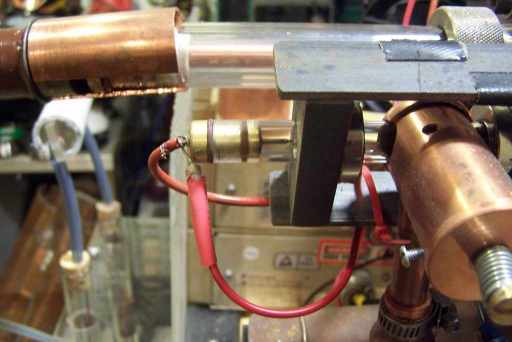 Here is how we let gas into the system. This also has the property that at very low system pressures, the pressure in the ion course is a little higher than that in the system as a whole due to limited gas conductivity through the quartz tube. To make it easier to control the gas flow, and to keep the pressure higher in the upstream plumbing, I used a piece of capillary tubing at this spot. This particular piece is about 1.5" long by .007" ID, which frankly, is on the "too much flow" side, and for comparison, another one I made was about 2" long by .005" and was on the "too little flow" side of things. I got the SS capillary tubing at McMaster-Carr. After cutting it (and I don't care how) you have a piece with both ends plugged, and careful sanding will not open them back up, the metal keeps smearing across the holes. So, what is done is to electropolish it, using a solution of phosphoric acid, sulfuric acid, and glycerin, about 4:1:1 ratio, with the tubing as an anode and a lead sheet as cathode, at around 5 volts DC until you point the ends and open up the holes. After this, a quick blast of compressed air gets all the gunk out of the tubing so it doesn't dry and plug it back up again. This is soft soldered into the piece of brass I turned on the lathe to fit the tubing and O rings. The back O ring isn't a seal, it's just a cusion to even out the pressure on the tubing from the end cap when under vacuum. You have to use low temp soft solder or you risk building up oxide in the SS tubing that will plug it up. Both the gas and the ion extraction "push" voltage come in at this point. I used a 27k series resistor on this to protect the little power supply I use, for example, when an arc from the main HV hits this point, and that's enough for that -- it must be a fairly rugged little supply as I've had that burn that resistor out a time or two until I got religion and made a polycarbonate box around this part. The other electrode that gets a negative voltage on it is simply a piece of 1/2" thick wall Al tubing, turned down to fit inside the quartz at the other end, with about 1/4" of the tubing extending past the quartz tubing end. This is done so that any sputtering that happens won't make the end of the quartz tubing conductive and cause a short in the tank, and Al was chosen for this as it sputters about the least of the practical materials you can get.
The ion extraction power comes from a 12 volt input, 1000v output CCFL inverter I get from DigiKey. This particular one is designed to drive two CCFL tubes, and is capacitively coupled on the output, very simple and cheap. I use the two caps as the series caps in two opposite polarity voltage doublers and get about plus and minus 3kv out of it with full input. To vary this I used an LM 317 regulator in a circuit with a pot to adjust the input volts to the inverter. The only downside of that is that below a certain input the inverter won't run and it jumps from zero output to about plus/minus 300v when it starts. Just now that's a problem for me as I'm doing something for which the amount of ions at 300v is too much, and at zero not quite enough, so I will improve that part soon. The part number for the one I'm using is 289-1025-ND at digikey, the manuf part number is BXA-12529. Note, grab these while you can, the advances in the tech are such that these are becoming scarce. All the new types are pwm for brightness control and will not work with simply varying the input voltage. And with PWM the output voltage peak is always the same as seen by a simple rectifier/filter combo. So, the new ones cost more and don't work as well for this. I get them 10 at a time, as they are also the cool thing for detector power supplies, and other low power things at medium high voltages. Very easy to get low noise DC out of them as they switch at about 60khz, so not much capacitor is needed.
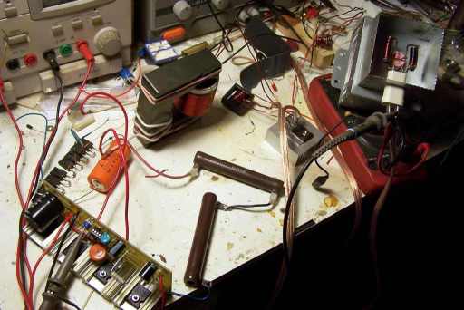 Now for the part that is magic, though it may not seem like it. Teasing something that was designed only for pulse mode into working in CW mode is in this case, quite a trick. Here is one of the power supplies I built to find out how, but once I did find out, I figured out how to not need this level of complexity. This one is a switcher at arounc 70khz with a voltage multiplier on the output, with current to the output limited by a selected series capacitor in the HV doubler. It turns out that this runs at about 8 volts per turn on that too-big transformer core, and so you need to make anothe step down transformer to get to the 3.3 volts the magnetron wants for filament power, at 10 amps or so. And it also turns out that magnetrons do not like AC filament power at that frequency one little bit, the lossy chokes they put in the filament leads internally burn up. So I had to make a centertapped autoformer driven off one turn on the big transformer, then rectify that with shottky diodes, what a pain, and at 10 amps, they need heatsinks too. Great learning experience! But not needed once you know what you want for the tube. It turns out that what you do want for this is a constant current type supply for the DC that will do about 4.1 to 4.3 kV and not quite full filament voltage, you want about 3 volts there, and there are other, much simpler ways to get that. Why this hassle? It's because in a magnetron, running under normal pulsed conditions, builds up electrons during the pulse, and many of them wind up hitting the filament again, heating it up, so even in that mode they don't use the full filament voltage to heat the thing, to compensate. If you try to run one CW, these electrons can just continue to build up and heat the filament further, not to mention that at some point they start inihibiting the oscillations themselves. Luckily, most mass production magnetrons have the magnetic field not quite straight, and this gives the electrons an escape path, spiraling out of the top or bottom of the internal resonator. In fact, if you are unlucky and get a perfect one, you'd have to add a magnetic error (shim) to get that condition, or it won't go CW at all. I wound up using a more conventional supply, slightly different than the stock one in the oven to get there, which is by far simpler (And cheaper too! Yay!).
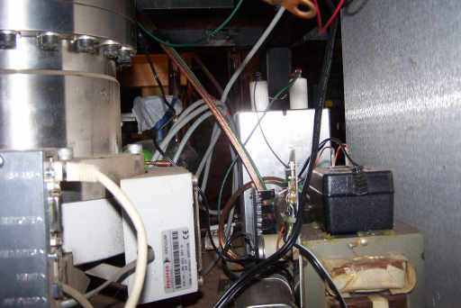 Here is a not very good picture of what I wound up with, schematic is next. This uses the regular magnetron oven transformer with some other tricks to get us there. The key is using a much smaller capacitor in the series leg of the voltage doubler, about 1/10 of what was in the oven, and another diode and filter cap to produce DC rather than pulses out of the supply. This picture stinks because of where the thing is -- in the inside of my cart, and it's there for a very good reason. The charge on the output filter cap is lethal! Or close enough, I got zapped by that once when it was up top, and it was pretty bad, so down it goes where I can't touch it by accident. Added to this stuff, there is a 15v supply to run the fan that is strapped to the magnetron to keep it cool, you still need that as the filament power alone will get one hotter than it's specified for, even though we're only pushing 20-50w DC into it, and most of that goes right back out as RF at 2.45 GHz. I used a computer case fan for that part, just held onto the magnetron with some wire, works fine, and the wall wart supply I used can run a couple of these fans, one of which also cools my feedthrough since it was meant to conduct heat out of the tank, and it gets hot sometimes too.
 Sorry about the sloppy drawing, but this is simple indeed, once you know what you are going for here. The series cap I show as .1 uf, which is on the large side for this, .068uf would be better. I used a bunch of 1.5kv 6A diodes in series for the rectifiers, a DigiKey part for TV flyback dampers (now obsolete -- hint people, grab all the CRT type tech you can while you can still get any of it, it's going away fast). I happened to get some big georgous neon bulbs at HEAS last time, so I used one as a current monitor on this. The variac is required and the setting is moderately critical. Too high and the thing goes in and out of oscillation as the electrons build up in there, and too low and it's either not enough power to do the job, or it just doesn't go at all. This setting is very near the point where the transformer begins to saturate and draw actual power even at no load, I didn't drive out the magnetic shunts even. I think you could substitute a 100-250 watt incandescent bulb for it and get about the same result, but haven't tried that yet to get a wattage number that is best. You want this for another reason, when run at full line voltage, the transformer itself will need a fan due to losses when in saturation, this way it runs cool as can be for hours on end. For now, I find it handy to have the variac there, if it gives a little trouble starting up, we put the ion extraction volts at max (which makes kind of a Penning source anyway) and jiggle the variac a little, then put it back when it starts. You can easily tell when it's right by the glow in the gas.
I got the magnets at Amazing Magnets but right now they are not listing the exact thing I got. Anything close should do, though, if you copy my pole piece design. Those are 1" by 1/2" pieces of iron on the ends, one of which is screwed to the top and bottom pieces that are 1" by 1/8" cross section, and the other one can be slid back and forth. If you look at the first picture closely, you can see a little shim I taped in there to hold it right once I got it adjusted.
Sorry about the sloppy drawing, but this is simple indeed, once you know what you are going for here. The series cap I show as .1 uf, which is on the large side for this, .068uf would be better. I used a bunch of 1.5kv 6A diodes in series for the rectifiers, a DigiKey part for TV flyback dampers (now obsolete -- hint people, grab all the CRT type tech you can while you can still get any of it, it's going away fast). I happened to get some big georgous neon bulbs at HEAS last time, so I used one as a current monitor on this. The variac is required and the setting is moderately critical. Too high and the thing goes in and out of oscillation as the electrons build up in there, and too low and it's either not enough power to do the job, or it just doesn't go at all. This setting is very near the point where the transformer begins to saturate and draw actual power even at no load, I didn't drive out the magnetic shunts even. I think you could substitute a 100-250 watt incandescent bulb for it and get about the same result, but haven't tried that yet to get a wattage number that is best. You want this for another reason, when run at full line voltage, the transformer itself will need a fan due to losses when in saturation, this way it runs cool as can be for hours on end. For now, I find it handy to have the variac there, if it gives a little trouble starting up, we put the ion extraction volts at max (which makes kind of a Penning source anyway) and jiggle the variac a little, then put it back when it starts. You can easily tell when it's right by the glow in the gas.
I got the magnets at Amazing Magnets but right now they are not listing the exact thing I got. Anything close should do, though, if you copy my pole piece design. Those are 1" by 1/2" pieces of iron on the ends, one of which is screwed to the top and bottom pieces that are 1" by 1/8" cross section, and the other one can be slid back and forth. If you look at the first picture closely, you can see a little shim I taped in there to hold it right once I got it adjusted.