Solder Reflow Oven in a Coffee Can
C-Lab Home
As we do some prototyping for customers, we obviously need the proper
tools to do that. One customer's needs involved building a very
tiny surface mount board for a prosthetic. These are very
laborious to hand solder under the microscope. It's about like a
700ft tall giant trying to pound in a toothpick using a pickup truck for
a hammer (and, as the pickup truck is too small for his fingers, he has
to hold it in giant tweezers). As this customer needed more than
the usual number of prototypes, we decided to streamline this process
somewhat and "do it right", rather than spending an engineer-day per
board to hand build them (which the customer was willing to pay for, but
try to find a truly willing engineer when it's just grunt work).
Vapor phase reflow theory:
Vapor phase reflow is a method of applying heat very quickly and
uniformly to something using a vapor. Usually what is being
reflowed is solder. Basically, a fluid is boiled at the bottom of
a tank, and its vapors rise into the tank. The top circumference
of the tank is usually actively water-cooled so any vapors that make it
that far are condensed and returned to the boiler via gravity. A
fluid is used that has a sharp boiling point, and a high heat of
vaporization, which means it gives up a lot of heat per gram when it
condenses on something. Water would for instance be ideal if you
wanted to heat something to exactly 100°C (or 97° C here in the
mountains). The industry uses specially engineered fluids for this
that have all sorts of desireable properties such as inertness (won't
corrode your stuff), dense vapor (won't come flying out of the oven),
high heat transfer, and good boiling behavior (no bumping or foaming).
We use FluoroInert FC-70 ®, a 3M
®product available from Acuity Sales (1-800-554-4905) for our
reflow fluid/vapor. The people at 3M specialty products
(1-800-810-8513) will hook you up with a local supplier if you
call. This stuff is VERY expensive, but it isn't consumed in the
process (when things are right), so it's not the most expensive part of
the production. For reference, we bought two 4 ounce bottles for a
mere $106.67. It looks like that may be nearly a lifetime supply
for this oven. It is an amazing substance that boils at 215°
C, has an enourmous heat of vaporization, and has a vapor about 28 times
as dense as air. As it condenses on whatever you're trying to
heat, it transfers heat very rapidly, but cannot heat the target
material above the magic 215° C boiling point. In fact, it
works so fast that the internals of the SMD parts never come close to
this temperature before the board is removed from the vapor.
Other techniques have been used for reflow soldering, including the
basic wave soldering setup, hot oil, IR, and convection. Vapor
reflow is considered the best by most, as the other techniques all have
problems. Regular wave soldering pretty much only does one side at
a time, and requires the components be glued down. IR has the
problem of uneven heating due to different IR characteristics of various
parts. The encapsulant used for IC's is IR transparent, but the
silicon inside isn't, so you can have the problem of the heat going
precisely where you don't want it. Convection using air or inert
gas heats more slowly as the gas doesn't have the heat capacity of a
vapor. This can lead to uneven heating of parts with varying
thermal masses. The attempt to overcome this by force circulation
of the gas can blow the parts around. Hot oil is messy.
This project:
For this size board (a segment of which is the background image here),
a little under 2" x 2", a coffee can is a perfect fit and has some nice
engineering properties for this application. The thin steel
is a lousy conductor of heat, perfect for a situation where you want
solder temperatures at the bottom and vapor all condensed before
escaping the can. Heat will go through the thin steel easily in
the thin dimension, but as far as heat transfer goes, the top of the can
may as well be insulated from the bottom. Steel is a fairly poor
conductor for heat, as any welder knows.
First, obtain a coffee can. This is easy here, as engineers tend
to like coffee. We used a Folgers can for mod 1.0 and a Maxwell
House can for mod 2.0. The Maxwell house cans have a lip around
the top that we haven't decided to declare good or bad yet.
Strip all the paint off the can, or you're going to have a lot of smoke
later. Paint stripper makes it easier, but it still doesn't just
come right off, you will need a wire brush in a drill or a lot of elbow
grease and sandpaper time.
Be sure to see: It Almost Worked for
this project, we had a ball with this one. This page will soon be
updated to remove most of the attempts that didn't work just so, or just
wasted time and materiels.
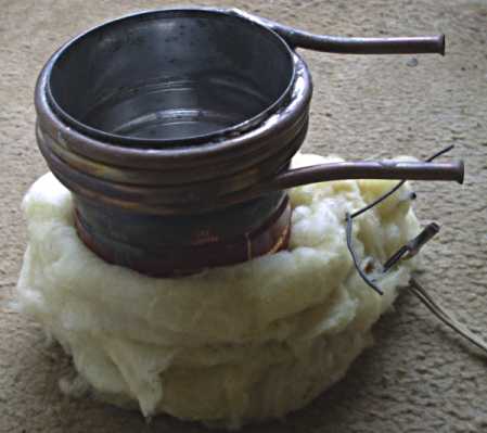 For the
first model, we wrapped 5 turns of 3/16" copper tubing around the very
top of the can for a cooling water flow. This was soldered to the
can, and flared to match our plastic water tubing size. It works
well, but anything that needs plumbing is a pain, so for the next model
we will try a passive heatsink made from copper flashing. In
either case, these are soldered to the can using the basic plumbing
tools for this. Get "refrigeration grade" copper tubing if you
can, as it is much easier to wind. You will not need very much
water flow, just a drip-drip does it fine, which is what inspired us to
try a passive finned heatsink for the next model. This model
works, but it works ugly.
Heat is supplied by a 100 watt insulated heating "rope" we happened to
buy cheaply as surplus. They normally cost too much for Doug to
design them into things. The rope is wound in a spiral at the
bottom of the can and glued with Silastic 650. The insulation is
to control the height of the resulting vapor column in the can, and to
prevent burning the bench. One of the ugly things about this is
that it is now mechanically unstable, and should have feet that protrude
through the insulation.
Here we use a trick that may be useful to others, and in other
situations that need water cooling. We put a gallon jug or 5
gallon bucket up on a shelf, filled with water and maybe some ice cubes
and antifreeze. Set up a siphon down to whatever you're water
cooling, and let the resultant coolant go into another bucket or
jug. We use a pinch valve we got from Small Parts Inc. to control the
flow. It takes suprisingly little water to handle most things,
like this or a distillation column. Often the water in the bottom
jug can just be poured back into the top when the top starts to empty,
as it has cooled to room temperature by then at these slow flow
rates.
At this point, you have a reflow oven. The power (100 Watts) is
just about right to simply plug the thing in. We usually use a
variac or a big dimmer for things like this around here. Unlike
model-1, model-2 seems to have a bit too much power, which I suppose is
due to better thermal coupling from the new heater than from the
glass-insulated wire rope of model 1, not to mention higher power with
the McMaster-Carr heater. We will need to control the power at
less than full up.
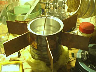 Six 2" x 4" pieces of flashing were cut out
and sweated to the sides of the can at the top. They get fairly
hot, which indicates that more would be good. We believe that in
this case, the plumbing may be worth the hassle. Here's the
completed reflow oven mod 2.0 in all its glory on our messy chemistry
desk just after its first run. The dryer hose coming in at the
right is exausting at around 300 cfm to catch anything that gets out of
the can, but it turns out to be precisely the wrong thing to do.
It disturbs the convection rotor in the can and sucks valuable
Fluorinert out, while mixing the vapor in the can with water vapor from
the fresh air. The wire going into the can is a type K
thermocoule, which the DVM at the bottom is reading. White fumes,
which aren't Fluorinert, start coming off at a rather low temperature,
this is either a decomposition product or an impurity. White
fumes, which aren't? Fluoroinert, start coming off at a rather low
temperature. It seems these fumes are some decomposition product
of Fluoroinert plus water vapor from the air. In a relatively
sealed system, there are no visible fumes. The version pictured
here used a heater from McMaster-Carr,
please do check out It Almost Worked
for more information on this model, and maybe a laugh or two.
Once the Fluorinert is bubbling merrily, lower your board into the
vapor near the bottom of the can. We use a cage made of baling
wire to do this here. The board will suddenly look wet, a sign
you're into the vapor. A few seconds later any solder on the board
will melt and flow, and the board will appear to (mostly) dry.
You'll want to hold it up near the top of the can for awhile to drain
every last drop of that expensive Fluorinert off before completely
removing the board. The actual Fluorinert vapor layer in the can
is colorless and invisible. You can only tell it is there by the
condensation on the can sides.
Model 2.0 works a little less ugly than model 1.0, but the
McMaster-Carr heater has too much thermal mass, and will create problems
for the eventual computer automation we plan to apply to this.
Thus yet another heater was tried, and it's simply perfect.
It is a 100 watt quartz halogen bi-pin bulb plugged into a ceramic tube
socket salvaged from some old surplus. I'm sure you can just buy a
socket for it, but there was no need here. The tube socket was
glued to the can bottom with the ubiquitous Silastic 650 and holds the
bulb about 1/4" away from the can bottom. We think it may work
even better without the original heat spreader we put on the can bottom,
and will try that next time. However, "too fussy wastes
man-hours", so for now we are using Model 2.1. (Quote is from Robert
Heinlien's "Farmer in the Sky") Here's what it looks like.
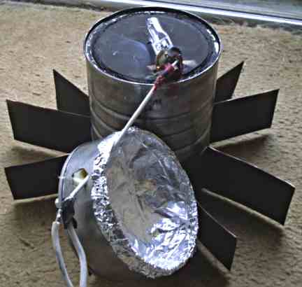
A base was made with the bottom of another coffee can, cut right in the
middle of a rib with the dremel tool and diamond wheel. This fits
nicely inside the base of the original can, and will be lightly glued
with hi-temp Silastic once everything is verified. Some
fiberglass was laid around the outer edge of the base, and an aluminum
foil reflector fabricated. Teflon coax (we had this laying around,
you could use other high temperature wire, or baling wire wrapped with
teflon tape for this) was crimped to the socket terminals with little
pieces of copper flashing. Can't use solder here! The base
has 3 4-40 standoffs used as feet, and they don't get hot due to the
insulation and reflector. We didn't mind holing the base, as it
doesn't have to contain liquid. This model runs fine with no
insulation wrapped around the main coffee can. The black paint on
the can bottom and fins is high temperature paint from the auto parts
store, which is meant for painting headers. Theoretically, this
should make it absorb IR and visible better, but who knows? In
other work we've been quite suprised to find that things that would seem
quite black are actually IR transparent, including carbon black used in
many paint pigments.
However, it is at this point that the real fun begins. For
the process to work well, you will need to preheat your board at a
particular time vs temperature profile. Your toaster oven isn't
slick enough for this job, even with a thermocouple and a variac (and
that's getting into grunt work again, shame on you). The profile
you want is from 1-2 degrees C per minute, heating to a temperature of
about 150 degrees C. This activates the rosin and gives it time to
work, effectively glueing the parts down to the board in the process.
Pre-heat oven:
What is needed is an integral preheat oven that doesn't expose the
board to cold air in between the steps. Our baling-wire board cage
will extend through some small holes in the top, so we can raise and
lower the board without opening the top at all. The wires will
have 4/40 nuts soldered on to prevent shoving the board all the way down
into the liquid. What is done is the board is preheated, then
shoved down into the Fluorinert vapor, then, when the solder has melted,
the whole top is simply lifted off so the board can cool.
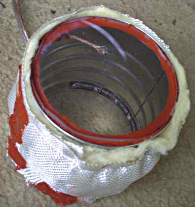
This was made with the rest of the can left over after cutting the base
off. Like the base, the fact that it was cut off in the
middle of the rib means it fits into the main can nicely. A 1/4"
thick piece of Lexan (Lowes) serves as the top and as a window.
Near this window, you can see the thermocouple entering at the top
left. This is just plain old type K thermocouple wire, obtained at DigiKey, with the end twisted and then
welded with an oxyacetylene torch. We tried Mapp gas, but without
the oxygen, it just wasn't hot enough to melt the wires. You can just barely make that work if you
hold the wires just above an anvil while heating with the Mapp, and hit
them with a hammer while orange hot. It might take more than one
try. Ringing the bottom of the can are 12 1.0 Ohm 3 watt
Ohmite "vitreous enamel" resistors (DigiKey again) hooked in
series. These can indeed be run well above their ratings without
harm. Fiber shoulder washers and just plain washers insulate the
resistor leads and the 4-40 screws from the can. As the heating
power is marginal with a 24 volt supply (at least while sitting on those
heatsink fins), a thin layer of insulation was wrapped around the can
and secured with fiberglass cloth (boat store), rubber bands, and the
ever handy Silastic 650. We plan to add a pair of 20w, 12 volt
halogen bulbs to this for more heat and useful light, after brazing some
wire to the bases of them. No solder used here either. The
white arc on the Lexan is a bruise from an earlier use of it for
something else. Why waste the good stuff on prototypes?
Small holes will be drilled into this to admit the baling wire board
cage handle. For this part of the job, the Maxwell House can lip
is definately good.
A run with this showed us something new. No white fumes appeared
at all. It seems the Fluorinert doesn't like being mixed with
fresh air (water vapor?), and with this on top of the main can, there is
pretty much no circulation. For whatever reason, this solves that
problem anyway, and losses of Fluorinert are very tiny.
We designed a PID controller for this project based on a MicroChip
18LF452. Digikey sells type K thermocouple wire, and LTC1152
no-drift opamps (and most of the other parts). Cold junction
compensation will be done digitally using data from a TI TMP 100
I2C temperature sensor placed near the terminal block used for external
thermocouple connections. We use the ICD-2 and the Hitech
PIC18 C compiler for things like this, reusing software we've written
over the years to speed things up. It is always easy to go "up" in
PICs, and often easy to go down, if the more advanced capabilities of
the later family aren't used by the code. This controller has 2
thermocouple inputs, a solid state relay to control the main heater, and
a FET driven by a PWM source on the PIC chip for the pre heater.
We added a communications link to talk to a PC or other host, and ran
the various spare PIC pins out to terminals for later use (you never
know). A 16x2 LCD display and a few pushbuttons for settings round
things out. The whole thing, including a massive power
transformer, fits easily in the large project box from Radio
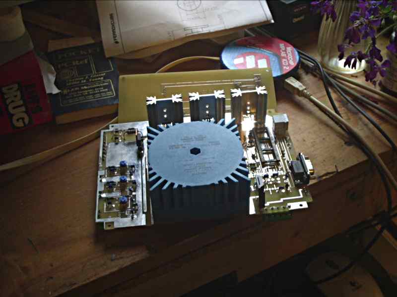
Shack. Here is a picture of the partially stuffed board. The
unstuffed front panel board is behind it. The wiring terminals are
stuffed on the bottom of the board to make drilling the clearance holes
in the project box easy.
One of the thermocouples is used to monitor the preheat temperature,
the other is used to know when the vapors have risen in the can to
working height. There's no point in boiling the Fluorinert the
whole time, so the main heat will only be turned on when the preheat
cycle is nearly complete. The solid state relay
in the controller will allow for proportioning the main heater.
The big transformer is for a large 24 volt DC supply that is
PWM-switched by an onboard FET into the preheater resistors. Frank
did the layout work here, ain't it purty?
We plan to make this design available to all under the GPL. "Send
a self-addressed, stamped email" for the files.
Here's the address as a jpeg for the nasty spambots to miss: 
(Note to self, more on this when the thing is finished and tested!)
All trademarks are property of their respective owners. Sorry if
I got too lazy to put in the little ® thing everywhere I could
have. These names are all well known by everyone in our business,
and we obviously have no interest in "stealing" them.
C-Lab Home
 For the
first model, we wrapped 5 turns of 3/16" copper tubing around the very
top of the can for a cooling water flow. This was soldered to the
can, and flared to match our plastic water tubing size. It works
well, but anything that needs plumbing is a pain, so for the next model
we will try a passive heatsink made from copper flashing. In
either case, these are soldered to the can using the basic plumbing
tools for this. Get "refrigeration grade" copper tubing if you
can, as it is much easier to wind. You will not need very much
water flow, just a drip-drip does it fine, which is what inspired us to
try a passive finned heatsink for the next model. This model
works, but it works ugly.
Heat is supplied by a 100 watt insulated heating "rope" we happened to
buy cheaply as surplus. They normally cost too much for Doug to
design them into things. The rope is wound in a spiral at the
bottom of the can and glued with Silastic 650. The insulation is
to control the height of the resulting vapor column in the can, and to
prevent burning the bench. One of the ugly things about this is
that it is now mechanically unstable, and should have feet that protrude
through the insulation.
 Six 2" x 4" pieces of flashing were cut out
and sweated to the sides of the can at the top. They get fairly
hot, which indicates that more would be good. We believe that in
this case, the plumbing may be worth the hassle. Here's the
completed reflow oven mod 2.0 in all its glory on our messy chemistry
desk just after its first run. The dryer hose coming in at the
right is exausting at around 300 cfm to catch anything that gets out of
the can, but it turns out to be precisely the wrong thing to do.
It disturbs the convection rotor in the can and sucks valuable
Fluorinert out, while mixing the vapor in the can with water vapor from
the fresh air. The wire going into the can is a type K
thermocoule, which the DVM at the bottom is reading. White fumes,
which aren't Fluorinert, start coming off at a rather low temperature,
this is either a decomposition product or an impurity. White
fumes, which aren't? Fluoroinert, start coming off at a rather low
temperature. It seems these fumes are some decomposition product
of Fluoroinert plus water vapor from the air. In a relatively
sealed system, there are no visible fumes. The version pictured
here used a heater from McMaster-Carr,
please do check out It Almost Worked
for more information on this model, and maybe a laugh or two.


