 Of course, you will have seen this picture on the front page and elsewhere, but here I will describe the rig some, and it's a decent picture for that.
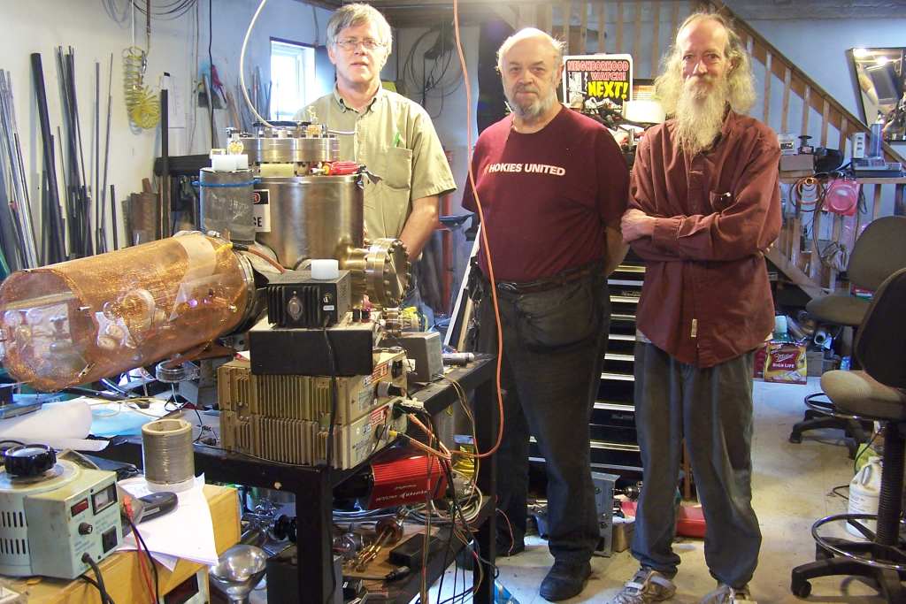
The big tank is one Bill found at a high tech scrap yard, it was once part of an electron microscope. I cleaned it out and added some things for fusor research, such as the Pfeiffer vacuum pump system, a 500 l/sec turbo, and a two stage UltraDry forepump, the mass spectrometer (0-200 amu) a viewport/door, and numerous flanges and feednthroughs and gaskets to make it complete, or nearly so. It's good enough to do real work in at present. This picture was taken before we added a lead dress to the entire tank for gamma rays, and before we got the 3He tube and the nifty new Spellman SL2KW power supply which makes 50kv at 40 ma (actually, it easily makes more, but those are the specs). For these runs, we used a smaller Spellman PTV-200-class supply, which puts out 40kv or so at about 12.5 ma, it's the lower one in the stack on the table on the lower right. As with most ebay items (we really stole that pair for $179, and thanks Bill for coming up with these jewels, and Spellman for making great stuff that lives on and on) these didn't have the HV cable in usable form, so we made one from Accel ignition wire and the shield from RG8 class coax. Just a little adapter had to be made on the lathe out of PEEK for that one, no big deal. As you can see, the HV business end is in a Cu screen shield for our safety. Whenever we get things stable for awhile, that screen goes on there to keep the lightning away from us, but allow us to see in and troubleshoot any corona or arc problems. The screen is held on by a hose clamp on the flange it mounts to, which also grounds it well. You can see our microwave ion source lighting up in there, and our HV feedthrough with the coil ballast and neon bulb on the end. Atop the stack of Spellmans there is a CCFL based plus and minus 2kv variable supply for detectors and the like, and on top of that the 12v regulated supply that runs it. Not seen in this picture is the control panel for the Pfeiffer station and gage readout I inlet into the table top on the side we are standing on. You'd think that for that money they'd have backlit the LCD display, but nope, and that's a constant hassle when running in the dark so we can see in there and take better pictures. Funny, they didn't seem to mind using hideously expensive (but reliable) connectors, so that penny pinching seems out of character. The forepump has some shake, so it's mounted on the bottom on rubber isolators, and we added maybe 200 lbs lead to that platform. The turbo is mounted on a bellows, so the tank is pretty vibration free and it's all quiet running. The system easily reaches e-8 mbar when we don't have any plastic tubing involved in the gas plumbing, even though the froot door has a viton seal and there are a couple of viton type tubing couplers on there. But everytime we add even one more inch of viton, the base pressure goes up, so we keep that to a minumum so far as possible. On the corner of the wood table in front you can see the IR thermometer we use to keep track of tank temperatures duing runs. You can also see an early version of our neutron oven/moderator we use to activate things like silver for integrating neutron flux measurements. We've since improved that due to some advice from Frank Sanns to not use PVC as the moderator, and the new HDPE one does work better, and has more places to insert samples at various moderation levels for testing. The oven is sitting on the flange stub just above the screen, and kind of obscures the "danger high voltage" sign we put on there. No problems with that; we know better than to stick fingers too close! Just below and to the right of the oven, you can see a bend in the little bit of lead we wrapped the stub in, which is where we insert our BTI bubble dosimeter during runs to get some idea how we are doing. At this point, we're making another holder farther away, because we are ruining them fast with too many neutrons. As Curtis Faith said, "nice problem to have". We hope to have him here in other than email form at some point to help more, with this and with our shared interest in market trading as well, which is where most of the bucks come from to fund our efforts.
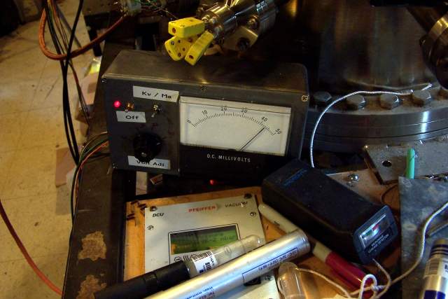 Here is the left front table/panel of the big rig. You can see the Pfeiffer controller, a couple of BTI's and the microwave leak detector we used to test our ion source, and no, it doesn't leak as much as a new microwave oven does, reads "nothing" on that meter, where a new oven does read up some on it. Nice to know. As we got the Spellman's surplus, we had to jin up our own little control box for them and you can see that and its meter here. This was quite simple to make, we just used a 9v battery to provide control voltages for the supplies, and a standard meter to read the voltage and current outputs, along with a switch to enable/disable the HV and an indicator led so we know when to NOT work on the back side stuff. We often run without that safety screen on there when we are making a lot of changes, so this is important. The meter calibration is about 5% high here compared to a professional high voltage probe, but we know that and correct in our reports. Ditto the Pfeiffer pkr-251 gage we read here -- it is known to read high on air, much less deuterium, but the numbers are very repeatable, and the cap manometer we got surplus is very flakey by comparison, so we continue to use this one as the standard, even knowing that when it's saying something like 2.2 to 2.5 e-2 mbar, it really means something more like the 16-20 microns Richard Hull reports for his runs. With some experience, you can tell by how the discharge looks, the relevant effects only happen in a range so narrow you could use it to calibrate gages, to tell the truth, once you are familiar with a given setup. So when we report pressures, please take this effect into account.
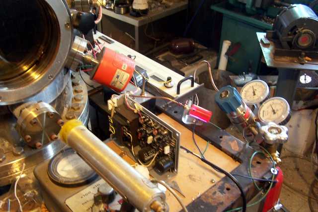 I cheated a little and just took this picture today (2010-2-1) as we'd forgotten on the exciting day of the neutron club runs, and nothing has really changed that much -- nothing in the gas handling system I'm showing here. We transferred some deuterium from the large tank to the little red lecture bottle strapped to the side of the cart, and the day glo red knob is the little needle valve we use for coarse flow control. The very nice two stage regulator on the tank is from Matheson Tri-Gas, where we got the deuterium. As you can see, all the gas plumbing is Cu tubing, except for a short 8" piece at the back, not shown, which even when painted with glyptal, that piece of silicone tubing raises the tank base pressure from <e-8 mbar and below to 1.4 e-6 mbar. So when Richard Hull says "use all metal plumbing" that's not a joke. For this design, though, we needed electrical isolation for the gas inlet which gets charged to about a kv to help push ions out of the ion source into the tank. We will try and find something better, of course. In this picture you can also see the Victoreen 493 geiger counter we use for safety in front of the window, the flakey capacitive manometer and supply for that, the ion extracion power supply (little box) and behind that, the dandy new Spellman SL2KW we use now, but not that day -- we didn't have it yet on 10/30/2009 when the rest of this happened. Note, when we run, we at least have a thick piece of leaded glass in front of that viewport, a 3/8" thick piece of sacrificial pyrex behind it, and more often than not, a piece of 1/8" lead over the whole thing except when taking pictures. The X rays coming out of this can be pretty fierce, and we try to keep doses down here.
I added a "clicker" to the victoreen geiger counter so I don't have to be looking at it to know if something is going on. I also like big analog meters for quick reading of order of magnitude at a glance. There's just too much going on during a run to set things up where you have to squint at several things in turn to see what's going on right now -- by the time you get to the last one, what you saw on the first isn't there anymore. That part is all getting automated now, and put into a MySQL database during runs, so future reports will be a little more quantitative in nature. For nearly all runs, we just open the tank valve once, close it again, and run on the gas in the regulator from then on. You get maybe an hour's worth that way, and a reduction in accident possibilities.
I cheated a little and just took this picture today (2010-2-1) as we'd forgotten on the exciting day of the neutron club runs, and nothing has really changed that much -- nothing in the gas handling system I'm showing here. We transferred some deuterium from the large tank to the little red lecture bottle strapped to the side of the cart, and the day glo red knob is the little needle valve we use for coarse flow control. The very nice two stage regulator on the tank is from Matheson Tri-Gas, where we got the deuterium. As you can see, all the gas plumbing is Cu tubing, except for a short 8" piece at the back, not shown, which even when painted with glyptal, that piece of silicone tubing raises the tank base pressure from <e-8 mbar and below to 1.4 e-6 mbar. So when Richard Hull says "use all metal plumbing" that's not a joke. For this design, though, we needed electrical isolation for the gas inlet which gets charged to about a kv to help push ions out of the ion source into the tank. We will try and find something better, of course. In this picture you can also see the Victoreen 493 geiger counter we use for safety in front of the window, the flakey capacitive manometer and supply for that, the ion extracion power supply (little box) and behind that, the dandy new Spellman SL2KW we use now, but not that day -- we didn't have it yet on 10/30/2009 when the rest of this happened. Note, when we run, we at least have a thick piece of leaded glass in front of that viewport, a 3/8" thick piece of sacrificial pyrex behind it, and more often than not, a piece of 1/8" lead over the whole thing except when taking pictures. The X rays coming out of this can be pretty fierce, and we try to keep doses down here.
I added a "clicker" to the victoreen geiger counter so I don't have to be looking at it to know if something is going on. I also like big analog meters for quick reading of order of magnitude at a glance. There's just too much going on during a run to set things up where you have to squint at several things in turn to see what's going on right now -- by the time you get to the last one, what you saw on the first isn't there anymore. That part is all getting automated now, and put into a MySQL database during runs, so future reports will be a little more quantitative in nature. For nearly all runs, we just open the tank valve once, close it again, and run on the gas in the regulator from then on. You get maybe an hour's worth that way, and a reduction in accident possibilities.
 Here are some of the grids we've used here. The one used for this run is the one in the middle, which is 1" OD, and about 2" long between the end caps. All the grids shown here are all titanium, pure. Believe it not, the one on the left still works, even after getting a bit too enthusiastic on the power with the new supply we have now, just a little weird. The one on the right is the ourter vane grid from the two grid system we're playing with still. On the lower left, you can see the sacrificial window protector we clip in behind the expensive viewport/door to keep it from being sputtered on, and a little chunk of BGO we set on the lip of the door flange inside to monitor charged particles and X rays. I don't think we turned it dark with X rays alone, that's probably just some sputtered metal. The glass, however, has browned from X rays, so hey people -- do be careful, that means one heck of a lot of X rays and charged particles have hit this. I kind of expect to see it blow into a Lichtenberg figure someday.
As you may guess from the picture, our standoff is made with a 10-32 tapped hole in the end to support grids, it's a nice system. The clips that hold the protective window were made here from beryllium-copper alloy. In the back you can see a piece of "India Glass" (known as mica outside of the McMaster catalog) we sometimes used to keep grid material from sputtering onto the insulator of the feedthrough, with kind of mixed results.